IINTRODUCTION
Refrigeration
is the science of producing and maintaining temperatures below that of the
surrounding atmosphere. It finds application in almost all fields for the purpose
of temperature control. Until the beginning of the twenty-first century, CFC’S
were widely used as refrigerants. The use of CFC’s is banned acknowledging its
harmful effects on the environment. This led to the evolution of HCFC’s and
HFC’s. However these too have disadvantages. Both have high cost of production
and contribute to global warming. The development of alternative cheap and
green refrigeration techniques has thus become the priority for the future.
Thermo Acoustic Refrigeration (TAR) is one such green idea for refrigeration.
Lord Rayleigh [1] was the first to give a thoroughly qualitative description of
thermo-acoustic effects in 1887. After this, the subject remained untouched
until 1970 when scientists like Rott, Hofler and G. W. Swift signaled its
revival with their research on TAR.[1]
Thermoacoustic deals
with thermal effects of the sound waves and the interconversion of sound energy
and heat. Sound waves travel in a longitudinal fashion. They travel with
successive compression and rarefaction of the medium in which they travel (gaseous
medium in this case). This compression and expansion respectively lead to the
heating and cooling of the gas. This principle is employed to bring about the
refrigeration effect in a thermoacoustic refrigerator. [2]What is a Thermo-Acoustic?
Thermo-acoustic is a branch of acoustics and
thermodynamics, which studies the movement of heat by sound waves. Acoustics
deals with the study of the effect of sound transfer, like pressure changes and
motion oscillations, whereas thermo-acoustic deals with temperature
oscillations. Thermo-acoustic,
deals with how sound energy converted into heat or vice versa. A basic
knowledge of sound and heat transfer is a prerequisite for better understanding
of the TAR. [1]

Fig.1.
Thermo-acoustic refrigerator setup
WORKING PRINCIPLE
Thermoacoustic Refrigeration System mainly
consist of a loudspeaker attached to an acoustic resonator (tube) filled with a
gas. In the resonator, a stack consisting of a number of parallel plates and
two heat exchangers are installed. The loudspeaker, which
acts as the driver, sustains acoustic standing waves in the gas at the
fundamental resonance frequency of the resonator. The
acoustic standing wave displaces the gas in the channels of the stack while
compressing and expanding
respectively leading to heating and cooling of the gas. The gas, which is
cooled due to expansion absorbs heat from the cold side of
the stack and as it subsequently heats up due to compression while moving to
the hot side, rejects the heat to the
stack. Thus the thermal interaction between the oscillating gas and the surface
of the stack generates an acoustic heat pumping
action from the cold side to the hot side. The heat exchangers exchange heat
with the surroundings, at the cold and hot sides of the stack.[2]

Fig.2
Schematic representation of construction of thermoacoustic refrigerator.
Above
represented figure shows the schematic representation of the construction of
thermoacoustic refrigerator where the loudspeaker is used as a driver, the
resonance tube sustains the standing wave.
The heat exchangers are used so that
heat interaction with the surrounding takes place. Heat is pumped from the cold
end heat exchanger to the hot end heat exchanger. It is known that sound waves
are longitudinal waves. They produce compression and rarefaction in the medium
they travel. Maximum pressure occurs at the point of zero velocity and minimum
pressure at maximum velocity.[2]
DESIGN AND FABRICATION OF TAR
The experimental model of TAR mainly consists of
resonator, Stack(regenerator), working gas, end plugs, heat exchanger and acoustic
driver. Each component has been explained in the following sections.
Working Gas
In order to get more thermo acoustic power a high mean pressure, a high velocity of sound and a large cross-sectional area are required. For this reason, helium is commonly used in thermo acoustic devices. Helium’s velocity of sound is much higher than that of air and helium will not condense or freeze at low temperatures. The thermal conductivity of gas should be high as well, and the Prandtl number should be low, since a low Prandtl number would mean low viscous losses. [6]Acoustic Driver
The total acoustic power used by the refrigerator is provided by an acoustic driver. A significant portion of this power is used to pump heat in the stack and the rest is dissipated in different parts of the refrigerator. A higher performance of the driver leads to a higher performance of the whole refrigerator system. The accoustic driver converts electric power into accoustic power. The most common loudspeaker is of electro dynamic type which uses copper wires and permanent magnet. A loudspeaker with maximum power of 10 watts and 5Ω at the operating frequency of 360 Hz was selected as the acoustic driver for this study.[6]
Fig.3. Acoustic Driver
Acoustic Resonator (Tube resonator)
The
shape, length, weight and the losses are important parameters for designing the
resonator. Length of resonator is determined by the resonance frequency and
minimal losses at the wall of the resonator. The length of resonator tube corresponds
to quarter of the wavelength of the standing wave is:
L=λ/2 λ=a/f
Where,
a is the speed of sound in m/s, λ is the wavelength
in mm and f is the resonance frequency in Hz. The viscous and thermal
relaxation dissipation losses take place within the distance equal to the
thermal penetration depth, from the surface of the resonator. For the resonance
frequency 360Hz, the length of resonant tube was set equal to 240 mm that corresponds
to the quarter wavelength of the acoustic standing wave, the diameter of the resonator
tube was set equal to 20mm. [6]

Fig.4. Resonator Tube
Stack
The stack can be used
to convert heat into acoustic power and vice versa, The amount of heat that can
be converted into acoustic power (and vice versa) depends on certain aspects of
the stack, like material properties, stack dimensions and the position of the
stack in the tube. The stack material
should have a high heat capacity and high thermal conductivity in the y
(longitudinal axis) direction. The thermal conductivity in the (vertical axis) direction however, should be
very low. Heat pumping requires the heat storage and this requires high thermal
conductivity in the y (longitudinal axis) direction to be accessible. A low
thermal conductivity in x (vertical axis) direction is necessary to minimize
losses through conduction from hot to cold side. As it becomes clear, a
material with anisotropic thermal conductivity would be best. The length is
important for the temperature gradient. The length and cross sectional area of
the stack also determine how much the sound waves are perturbed.

Fig.5. Ceramic stack Fig.6. Glass tube stack
End Plugs
To make the resonator
end closed we have used an Aluminum plug to close the top end of resonator. As
it forms the end of the hotter region in the resonator, a metal like Aluminum
was chosen to absorb this heat and dissipate it to the environment.[6]
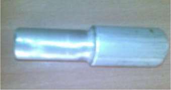
Fig.7. End plug
Modeling using DeltaE and Linear Approximations
For modeling and predictions on the behavior of
thermo acoustic devices DeltaE software is used in conjunction with the
approximations. DeltaE is the short form of Design Environment for Low- Amplitude
Thermo Acoustic Engines, is developed at Los Alamos National Laboratory. This
software can perform calculations on all kinds of acoustic devices using a
numeric approach. A text-based model of a device is built out of different
segments. These segments can be a tube, a heat exchanger, stack, speaker, etc.
The segments are written in sequence, corresponding to the actual location of each
part of the device. A set of guessed and target values have to be chosen by the
user to decide which variables need to be computed and which conditions must be
fulfilled. DeltaE tries to reach the targets by changing the values in the
guessed values. The guess values have to be chosen within an acceptable range
for the solution to converge. An initial model is mainly based on rough
estimates and certain constraints. With those estimations and constraints,
DeltaE can do initial calculations and based on those results, the user can
further change and optimize the model. [6]
Specifications of Thermoacoustic Refrigeration System
To
reduce the heat loss by conduction, resonator tube was constructed from
aluminum tubing with plastic tubing at
inner
portion. Helium was used as the working fluid. Parallel type stack made from
thermoplastic was used for this study.[2]
For
the design and operation of this thermoacoustic refrigeration system, used
parameters are as follows
·
Speed of sound in gas (He) = 1013 m/s
·
Gas specific heat =5193 J/KgK
·
Gas thermal diffusivity =13.2*10^-5 m2/s
·
Gas thermal conductivity = 0.155 W/mK
·
Gas dynamic viscosity = 197×10^-7 Ns/m2
·
Gas density = 0.8845 Kg/m3
·
Ratio of specific heats = 1.67
·
Normalized stack length = 0.262
EXPERIMENTAL SETUP
Model
setup with the connection to data acquisition system (DAQ) is a Speaker was
placed in the mount and the resonator on top of the speaker. For positioning
the stack inside the resonator tube, it slides from top end. It was pushed down until
its top was 47 mm from the top of the resonator. For positioning thermocouples across
the stack in the resonator tube, two small holes were drilled in the resonator.
Thermocouples measure temperature of hot and cold end of stack. To seal the end
of resonator tube aluminum cap was placed at the top of the resonator. For
operation of TAR model a signal generator and transformer is required. Signal
generator generates 400 Hz sinusoidal input signal to drive the speaker.
Amplifier was used to bring the signal up to the desired amplitude. This
amplified signal drives the speaker to create temperature gradient across the
stack.
The temperature difference was measured by the
thermocouples placed at either end of the stack. The output from the
thermocouples was given to data acquisition system (DAQ) for real time analysis
[1]
Fig.8.
Set up for prototype testing
DAQ-data acquisition
system RTD-resistance temperature
detectorsCOMPARISON OF THERMOACOUSTIC REFRIGERATION SYSTEM WITH VAPOUR COMPRESSION REFRIGERATION SYSTEMS
Apart
from vapour compression devices, there are several other ways to provide
cooling and refrigeration. Although none of these are currently as versatile as
a Vapour Compression Systems but some of these systems hold a high possibility
of replacing the pollution causing Vapour Compression Systems. Comparison with
various systems is as Follows,
The
Absorption Refrigeration uses a binary mixture of refrigerant and absorbent
like Water/ammonia or LiBr/water. The
Adsorption system uses natural refrigerants like water, ammonia or alcohol.
Thermo-electric and Thermoacoustic Refrigeration
Systems do not use any refrigerant.
Vapour Absorption
Refrigeration is a two stage process. The vapour refrigerant is absorbed in a
binary solution which then regenerates the refrigerant on heating externally.
It is cooled in the condenser to the required pressure level and the cycle
repeats. Much like the Vapour Compression Refrigeration Systems the Adsorption
Systems are also based on withdrawing heat from surroundings during an
evaporation process. Thermo-electric System is based on the Peltier Effect
wherein an electric current passing through a junction of two materials will
cause a change in temperature. The Thermoacoustic Refrigeration System is
powered by either a heat engine running on waste heat or an electric source. Due
to compression and expansion of air packets heat transfer across two mediums is
made possible. [2]Future prospective of thermoacoustic Technology:
It observed from former description that major
progress has done in stack. Though, the constant advancement in thermoacoustic
technology, entire world has increase speed of investigation. So far, it is
remarkable that major effort focus on research of stack, resonator and gas,
lack of experimental exploration of thermoacoustic refrigeration. Since earlier
result attained by researchers, it clearly noticed that a lot of variation
among thermoacoustic refrigeration performance with vapour compression
refrigeration in terms of refrigeration ability and temperature range.
Outstanding performance of stack and heat transmission is essential
Theoretical
investigation point out that the actual COP of thermoacoustic refrigerator is
based on performance of heat exchanger and stack. Also to make use of stack
substance to attain the requisite of perfect stack, still there is room for
development in structural design, mechanical design, combination of different
stack geometries (thin plates, flat plate with wavy, permeable filled element,
honeycomb with circular, wire screens, and so on). Further, the performance of
heat transport and flow distinctiveness like fluctuating flow frequency, flow
velocity, permeability of stack medium, and inside heat source is necessary to
the ability of refrigeration. In conclusion, heat transmits within stack and
heat exchangers should be improved to permit the heat produced via
thermoacoustic working fluid is transport as early as feasible.
Improvement in Resonator and use of different gas is required
The
research shows that the performance of thermoacoustic refrigeration system depend
upon the stack, resonator and gas. In most of research work, a constant
diameter resonator tube is used, and all researchers are concreted only on
resonator tube length, but the effect of convergent – divergent section based
on wave velocity is still not considered in resonator tube. By using convergent
– divergent section the velocity of gas can be increased, and this will help to
used low intensity sound generator which will help in reduce the input power.
In literature review
it is found that the most of the researcher’s used Helium as a working fluid,
and determined the influence of operational fluid on initial temperature
variation. But effect of various gases such as Nitrogen, Argon and different
gas mixtures such as helium-argon, helium-krypton, and helium-xenon on cooling
load is not studied. The use of convergent – divergent section resonator and
gas mixture should enhance the performance of thermoacoustic refrigerator.[4]
Main reasons to promote thermoacoustic refrigeration
- · Ecological concern and legislation which considerably limit or prohibit utilization of HFCs within less capacity, self-controlled refrigeration appliances.
- · Restrictions on usage of flammable refrigerant.
- · Few moving parts in thermoacoustic refrigerator, so it is very reliable
- · Thermo acoustic refrigerator have more long life span
- · Thermoacoustic refrigerator not producing any harmful chemicals like CFC,HCFC and HFC, so it is not harmful to the environment
- · Parts availability is more and having less cost. [2]
Disadvantages
-
· Efficiency is very less (maximum 40%)· COP of thermoacoustic refrigerator is less as compared to VCRS.[2]
CONCLUSION
REFERENCES
1] Demonstration
of Thermo Acoustic Refrigeration by Setting up an Experimental Model by Mathewlal T, GauravSingh ,
Chetan Devadiga, Nehal Mendhe, Mechanical Engineering Department, Fr CRIT, Vashi,
Mumbai. Mechanical Engineering Department, Fr CRIT, Vashi, Mumbai.
2] A Study of
Thermoacoustic Refrigeration System by Pranav Mahamuni, Pratik Bhansali,
Nishank Shah, (Department of Mechanical Engineering, Sinhgad Institute of
Technology and Science, Pune, India) Yash Parikh (Department of Mechanical
Engineering, Symbiosis Institute of Technology, Pune, India).
3] review of
investigations in eco - friendly thermoacoustic refrigeration system by Ashish
S. RAUT, Dr. Uday S. WANKHEDE Research Scholar, Mechanical Engineering
Department, G. H. Raisoni College of Engineering, Nagpur Professor, Mechanical
Engineering Department, G. H. Raisoni College of Engineering, Nagpur, India.
4] Investigation
of thermoacoustic refrigeration using a standing wave device by Jaydeep M.
Bhatt, Milan J. Pandya M.E. (Thermal Engineering), Department of mechanical
engineering, L. J. Institute of Engineering and Technology, Ahmadabad
(Gujarat), India.
5] Design and
Experimental Study of Small-Scale Fabricated Thermo-Acoustic Refrigerator by B.Ananda
Rao, M.Prasanth Kumar , D.Srinivasa Rao Asst.Professor, Mechanical Engineering
Department, ANITS, Visakhapatnam-531162, A.P, India.
Comments
Post a Comment